



Robotic Torch Positioning Tips for Optimal Welding Performance
 Aug 17, 2026|
 View:401
Getting the best weld quality in automated production requires exact torch alignment. You should set a basic 5 to 15-degree travel angle for regular joints. Fillet joints need a 45-degree work angle to spread the heat evenly. Careful positioning of your robot welding torch directly controls how deep the weld goes and how neat the bead looks.
Good alignment also reduces unwanted spatter and keeps the shielding gas steady around the weld pool. Choosing the right swanneck shape prevents your equipment from crashing during tricky movements. Automation engineers and technicians need clear rules to prevent costly mistakes right away. You can improve non-stop production work by learning these basic positioning skills first.
Key Takeaways
Keep a 5 to 15-degree travel angle to ensure clean weld beads and prevent messy metal spatter.
Use push angles for thin metal sheets, and use drag angles to melt thick steel plates deeply.
Set the torch angle using the robot wrist axes to keep all movements fast, smooth, and accurate.
Match the swanneck angles with your robot arm model to reach tight joint areas safely.
Adjust your Tool Center Point every day to make sure your welding paths are exact and to avoid expensive machine crashes.
Fundamentals of Robotic Torch Angles
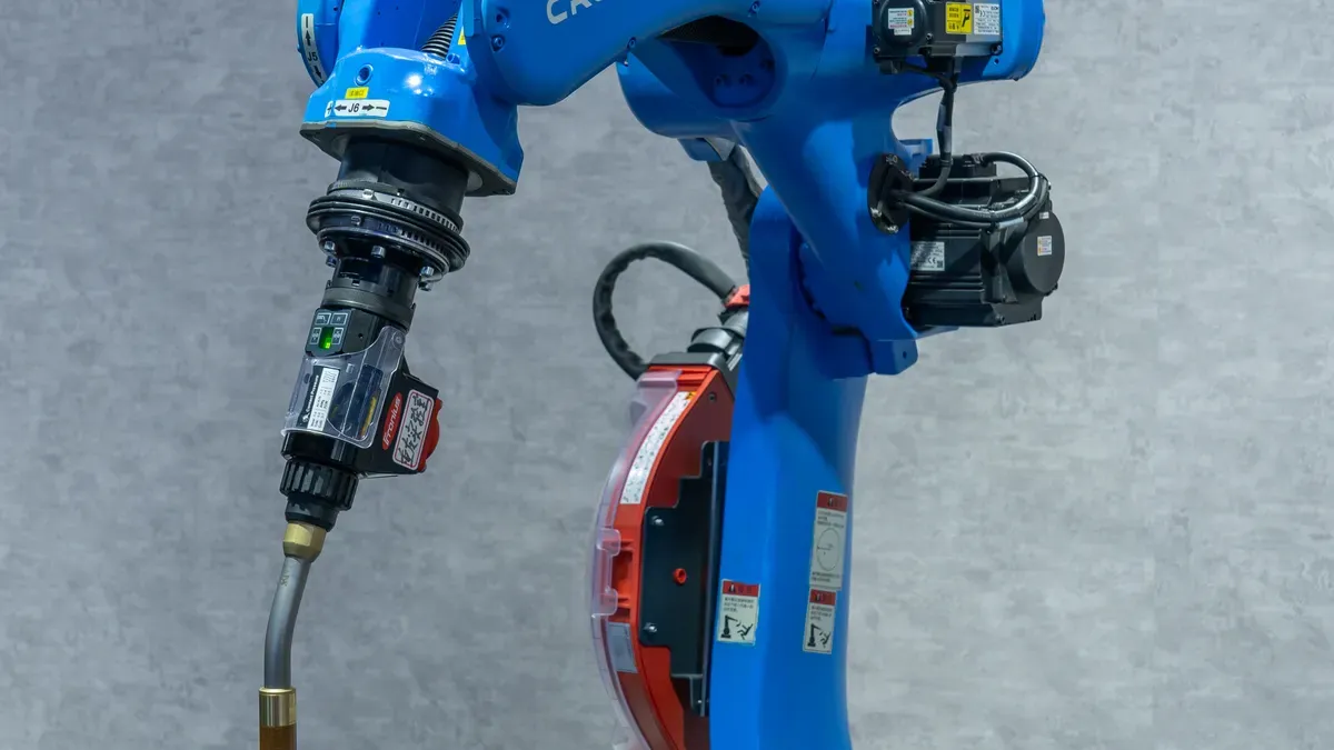
Travel and Work Angle Basics
You need to know two main angles when setting up an automated MIG welding cell for work. Work angle shows the exact place of your electrode compared to the joint surface. Travel angle shows the tilt of your torch compared to the movement direction. These foundational parameters are grounded in established GMAW technique guidelines[1] developed by the welding industry's leading standards body.
| Term | Technical Definition | Typical Setting |
|---|---|---|
| Work Angle | Angle between the electrode axis and the workpiece surface | 90° for flat butt joints; 45° for T-joints |
| Travel Angle | Gun orientation relative to the direction of travel | 5° to 15° push or drag inclination |
| Push Angle | Torch points toward the direction of travel | Pushes molten metal forward |
| Drag Angle | Torch points opposite the direction of travel | Pulls molten metal backward |
Exact torch alignment protects your total weld quality. Keeping robot positional precision near +/-0.02 mm stops incomplete joint penetration. Holding steady travel angles keeps your weld bead appearance even and clean. Correct orientation also steadies metal transfer to lower spatter generation. Steady positioning guards your shielding gas envelope against dirty room air.
Wrist Axis versus Major Axis Motion
You should set torch angle shifts with your robot wrist axes instead of major axes. Axes 4, 5, and 6 change orientation right at your Tool Center Point. Axes 1, 2, and 3 move the main arm body. Changing angles through wrist axes keeps torch motion fast, smooth, and exact while cutting extra arm movement and part wear.
Adding a 7-axis robot arm gives you one more direction choice than standard 6-axis tools. Normal 6-axis arms often lose torch angle control when moving around tight fixtures or long weld seams. A 7-axis setup bends easily past tool blocks, gets into tight spots, and stops dangerous arm jams. This extra freedom keeps your torch attitude smooth across tricky parts without needing extra stop-and-start moves.
Optimizing Welding Parameters and Torch Angles
Pick the right torch angle to control weld strength, heat levels, and how deep the weld goes. Changing this angle shifts how electric arc power hits your metal piece. You can improve your welding setup by matching torch angles to your joint design and plate size. Small position shifts change how molten metal flows and hardens while the robot works.
Push versus Drag Angle Profiles
A push setup points your robot torch tip forward toward where the arc is traveling. This style creates a wider weld bead that sits shallower on the metal. It spreads arc heat over a larger area, which keeps spatter low and leaves a smooth finish. In contrast, a drag setup points your torch tip backward away from your travel path. Dragging forces the arc energy straight down into the weld pool. This method makes a taller, thinner bead that penetrates deeper into your metal joint. However, dragging might create extra spatter if you do not adjust your wire speed and voltage properly.
A push angle works best for thin metal sheets because it uses a softer arc and gives a clear view of your joint. This setup controls overall heat and stops the arc from burning holes through the metal.
Use a push angle when welding thin parts or when you need low heat on weak pieces. Pick a drag angle when joining thick steel plates that need deep melting and heavy weld fills.
Joint-Specific Positioning Guidelines
Different joint types need exact angle settings to keep your finished welds strong and reliable. You must set your robot torch angles to match the joint shape to avoid surface flaws like uneven edges. Refer to industry-accepted welding procedure standards[2] for procedural guidance applicable across joint types and material grades.
For flat butt joints, keep a 90-degree work angle straight up from the metal face. Mix this layout with a 5 to 15-degree push angle along your weld line. This position spreads liquid metal over both plate edges while keeping your forward motion steady.
Fillet joints need careful torch placement so heat splits evenly between both metal sides:
| Parameter | Recommended Setting |
|---|---|
| Work angle | 45° bisecting the joint |
| Travel angle | 5–10° push (forehand) |
For standard fillet joints, set a 45-degree work angle right in the center of the corner. Next, add a 10 to 15-degree travel angle to push the weld pool smoothly. When dragging along a heavy joint, hold your torch at a 70 to 80-degree angle to the seam line. This exact range keeps liquid metal behind the arc, prevents weak spots, and melts both metal walls together completely.
Program these exact torch angles into your robot control system with care. Proper angle settings stop common welding mistakes, protect your tools, and keep your daily production running smooth.
Swanneck Selection for a Robotic Welding Torch
Overarm and Hollow Wrist Configuration
You must select the right swanneck geometry to match your specific robotic arm configuration. Overarm robotic installations require a precise mechanical setup to reach optimal weld joint access. Matching your torch neck angle with your mounting hardware gives you the correct work angle while reducing mechanical stress on your robot wrist axes.
| Component | Angle Contribution |
|---|---|
| 22-degree swanneck | 22 degrees |
| 23-degree offset mounting arm | 23 degrees |
| Combined approach angle | 45 degrees |
For standard overarm setups, you combine a 22-degree swanneck with a 23-degree offset mounting arm. These two pieces work together so their angles add up directly to 45 degrees. This exact parts match gives your welding torch an ideal 45-degree approach angle toward the target joint.
Hollow wrist arm designs require a completely different torch configuration. You use a 45-degree swanneck for hollow wrist robots to guide the internal cable assembly cleanly through the center of the robot arm. This specialized configuration prevents cable twisting, reduces wear on internal lines, and allows smooth wrist rotation during high-speed production cycles.
TCP Alignment and Mount Offset
Keeping exact positions from original robot programs is necessary during work; daily TCP checks and fixes protect your programmed welding path and torch angle during continuous use.
You must calibrate your Tool Center Point (TCP) with high precision before starting continuous automated manufacturing runs. Small TCP calibration errors alter your true torch angle during complex motion paths. Accurate TCP definition ensures your offline robot programming transfers directly to your live production floor with minimal manual path adjustments.
You need active TCP monitoring to detect small positional changes caused by tip wear, thermal expansion, or minor work cell collisions. Continuous TCP tracking preserves your programmed torch angles across long production shifts.
You should also install mechanical anti-collision mounts between your robot wrist and the torch body. These protective devices absorb sudden shock forces during unexpected collisions, protect your calibrated swanneck geometry, and maintain reliable torch positioning throughout continuous factory operations.
Preventing Weld Defects via Positioning
Shielding Gas Envelope Protection
You must keep a steady shielding gas cover around your liquid weld pool. Bad torch placement lets outside air mix with the hot metal. You can secure complete gas coverage by programming clean torch moves right into your robot controller path.
| Torch Positioning Adjustment | Robotic Welding Application | Effect on Porosity and Oxidation |
|---|---|---|
| Torch angle | Program 5–15° from perpendicular for vertical welds and 10–20° for overhead welds | Allows shielding gas to cover the pool and lets gas/slag escape, preventing gas entrapment and oxidation |
| Travel speed | Set robot travel speed to avoid turbulence while keeping the gas shield stable | Prevents atmospheric oxygen/nitrogen from being drawn into the molten pool |
| Standoff distance | Maintain a consistent nozzle-to-workpiece distance in the robot path | Ensures stable shielding gas coverage and arc stability |
Pay close attention to your front-end torch setup too. Picking a torch that flows gas well lowers air shaking during complex robot welds in hard spots. This steady airflow stops tiny holes, blocks rust, and keeps your electric arc smooth.
Eliminating Undercut and Excessive Spatter
Bad torch placement leaves ugly marks on your finished metal parts. An incorrect torch angle or bad stance above the metal pieces quickly creates deep undercut grooves. Fix undercut issues by shifting your torch angle and sliding the tool right over the joint center. Also, bad Tool Center Point calibration pulls your weld line away from the main seam. Recalibrate the robot arm and fix your torch angles to solve these tracking problems.
Bad gaps between your torch tip and metal pieces also create extra flying spatter while welding. Spatter flies straight into the nozzle and builds up around your contact tip. This thick crust inside the nozzle can snap cutter blades during automated reamer cleaning passes. Stop tool damage and cut repair delay by fine-tuning your torch work angle and travel stance.
Choosing a Strong Robot Welding Torch
Changzhou Golden Globe builds tough robot welding torches for carbon dioxide and mixed-gas automated welding jobs. Picking the right torch setup helps your automated factory line stay efficient and keep a steady arc. As global industrial robot deployments reach record levels[3], matching your torch specification precisely to your robot arm and application has never been more important.
Air and Liquid Cooled Solutions
Air-cooled torches give you a light and reliable option for many automated jobs. Models like the BW ROB350, BW ROB350GC, and BW 42G run at a 100% duty cycle and handle electric currents up to 500A. These torches use a replaceable gun neck and a strong aluminum body to endure tough factory work.
Heavy factory work needs extra cooling to handle very hot welding jobs. Liquid-cooled options like the BW ROB 501W, BW W500, BW 42W, and the BW 82W push-pull torch move heat away fast. These smart tools protect inside parts and maintain a steady welding arc over long shifts.
| Cooling Type | Torch Models | Current Capacity | Duty Cycle |
|---|---|---|---|
| Air-Cooled | BW ROB350, BW ROB350GC, BW 42G | Up to 500 A | Up to 100% |
| Liquid-Cooled | BW ROB 501W, BW W500, BW 42W, BW 82W | Up to 600 A | Up to 100% continuous |
System Integration and Consumable Fit
Your welding torches must connect easily to your robot arms and wire feeder units. This tool series works with wire sizes from 0.6mm to 1.6mm for different metal plates. These torches fit normal industry setups to make installation easy. You can pick internal crash guards like the iCAT mount for hollow-wrist robots or outer guards like the CAT3 PRO for regular robot arms.
Pairing exact parts with your torch protects weld quality and makes your equipment last longer. Well-made contact tips pass power smoothly and guide your wire right through the arc. High-grade gas nozzles keep your protective gas stream steady over the hot weld pool. Matching parts correctly stops wire jams, cuts sudden work stops, and keeps your production running fast.
Need a Reliable Robot Welding Torch for Your Production Line?
Changzhou Golden Globe manufactures professional-grade robot welding torches for CO₂ and mixed-gas automated welding — engineered for precision, durability, and continuous-duty performance.
Tell us your robot arm model and welding requirements — our engineers will recommend the right torch configuration for your setup.
Send an Inquiry →Getting the best performance from your automated welding setup means balancing your travel angles, work angles, and robot wrist moves. Using a 22-degree or 45-degree swanneck design helps your torch reach tricky joints easily and prevents your machinery from crashing.
Before you start production, go through this simple shop checklist:
Adjust your Tool Center Point (TCP) so your robot stays on its set path.
Check the distance from your contact tip to your work piece for steady arc voltage.
Test your shielding gas flow to ensure it completely covers the weld pool.
When you need durable industrial tools and exact torch position setups, you can rely on Changzhou Golden Globe. Our Robot Welding Torches deliver great performance and dependability for tough automated factory work. Visit our downloads page for product specifications and technical documentation.
Frequently Asked Questions
What travel angle should you set for automated MIG welding?
Set a travel angle from 5 to 15 degrees on basic joint setups. Using a push angle makes a wider, flatter bead while producing very little spatter. Choosing a drag angle pushes heat deep into heavy steel plates for the deepest penetration.
How do you choose between a 22-degree and 45-degree swanneck?
Combine a 22-degree swanneck with a 23-degree offset arm on overarm robots to hit a 45-degree approach angle. Pick a 45-degree swanneck for hollow wrist robots so internal cables pass cleanly through the center of the arm.
Why should you program angle changes using robot wrist axes?
Robot wrist axes 4, 5, and 6 turn right at your Tool Center Point. Relying on these wrist axes makes torch turns fast, smooth, and exact. This coding method stops extra arm motion and cuts tool wear down during fast factory runs.
What wire sizes do Changzhou Golden Globe robot welding torches support?
Changzhou Golden Globe robot welding torches fit normal wire sizes ranging from 0.6 mm up to 1.6 mm. These tough tools connect smoothly with common industry setups to give you steady electric arcs on busy assembly lines.
References
American Welding Society. "What Is GMAW? A Guide to Gas Metal Arc Welding." Welding Digest, June 2025. aws.org/magazines-and-media/welding-digest/wd-june-2025-what-is-gmaw/
American Welding Society. "Welding Codes and Standards." aws.org/standards-and-publications/codes-and-standards/
International Federation of Robotics. "Global Robot Demand in Factories Doubles Over 10 Years." World Robotics 2025. ifr.org/ifr-press-releases/news/global-robot-demand-in-factories-doubles-over-10-years
Bernard Tregaskiss. "MIG Welding Basics: Techniques and Tips for Success." bernardtregaskiss.com — MIG Welding Basics
Wevolver. "Robotic Welding." wevolver.com/article/robotic-welding
Blue Bay Automation. "Technical and Operational Benefits of 7-Axis Cobots in Welding Applications." bluebayautomation.com — 7-Axis Cobots in Welding
TZR Metal. "Sheet Metal Welding." tzrmetal.com/sheet-metal-welding/
Standard Bots. "5 Weld Programming." Welding Help. weldinghelp.standardbots.com/5-weld-programming.html
ABICOR BINZEL. "Robotic Welding Torch Swanneck: Breakdown, Build, Design, and Construction." blog.binzel-abicor.com — Swanneck Breakdown
Dynalog. "Maintain Robot Accuracy Through Production." dynalog-us.com — Robot Accuracy; "Robot Accuracy and Calibration Deep Dives." dynalog-us.com — Calibration Deep Dives
PatSnap Eureka. "How to Reduce Porosity Rate in All-Position GMAW Welding." eureka.patsnap.com — Porosity in GMAW
EVS International. "Robotic Welding Cell Components Integration 2026." evsint.com — Robotic Welding Cell Components